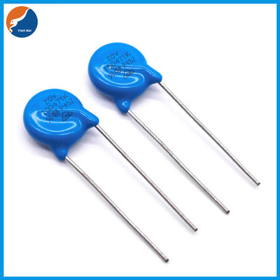
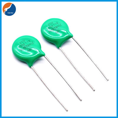
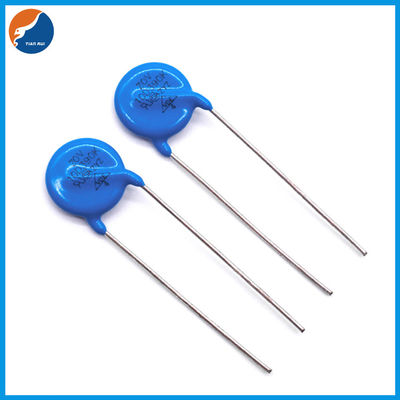
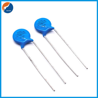
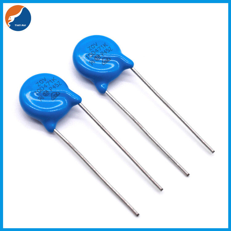
10D431K 10D471K Metal Oxide Varistor
Product Details:
| Place of Origin: | China |
| Brand Name: | TIAN RUI |
| Certification: | UL CSA VDE |
| Model Number: | 10D Varistors |
Payment & Shipping Terms:
| Minimum Order Quantity: | 1000PCS |
|---|---|
| Price: | Negotiable |
| Packaging Details: | Bulk or Tape&Box or Tape&Reel |
| Delivery Time: | 5-7 days |
| Payment Terms: | D/P,T/T,Paypal,Western Union |
| Supply Ability: | 1000000PCS/Month |
|
Detail Information |
|||
| Model: | 180K~152K | Coating: | Epoxy Resin |
|---|---|---|---|
| Lead: | Cp/Cu Wire | Electrode: | Silver |
| Disk: | Zinc Oxide | Solder: | Sn:96.5%CU 0.5%Ag3.0% |
| Solder Temp: | 245±5℃ | Immersed Time: | ≤5Sec |
| Operating Temperature: | -40℃ ~ +85℃ | Storage Temperature: | -40℃ ~ +125℃ |
| High Light: | 10D471K Metal Oxide Varistor,10D431K Metal Oxide Varistor,Zinc Oxide 10D471K Varistor |
||
Product Description
10MM Pitch Diameter Blue Chip Voltage Resistor ZOV Metal Zinc Oxide Varistors 10D Varistor
About Varistor
The varistor is a kind of voltage limiting protective device. Using the nonlinear characteristic of the varistor, when the overvoltage appears between the two poles of the varistor, the varistor can clamp the voltage to a relatively fixed voltage value, so as to realize the protection of the back stage circuit. The main parameters of the varistor are: varistor voltage, flow capacity, junction capacitance, response time, etc.
The response time of the varistor is NS class, which is faster than the gas discharge tube and slightly slower than TVS tube. Generally, the response speed of the over-voltage protection used for electronic circuits can meet the requirements. The junction capacitance of varistors generally ranges from hundreds to thousands of Pf. In many cases, it is not suitable to be directly used in the protection of high-frequency signal lines and ac circuit, because the junction capacitance will increase the leakage current, which needs to be fully considered in the design of the protection circuit. The flow capacity of the varistor is larger, but smaller than that of the gas discharge tube. Voltage sensitive resistor (VDR) is a kind of nonlinear over-voltage protection semiconductor device sensitive to voltage.
(1) Distinguish voltage sensitive resistors for power protection from those for signal line and data line protection, and they should meet the requirements of different technical standards.
(2) According to the different continuous working voltage applied on the varistors, the varistors used across the power line can be divided into two types: AC or DC. The aging characteristics of the varistors under these two volt-age stresses are different.
(3) According to the dffrent characteristics of abnormal overvoltage borne by the varistors, the varistors can be divided into three types. surge suppression type, high power type and high energy type.
![]()
| Table1 | ||||||||||||||
| Unit:mm | ||||||||||||||
| Symbol | Dimension | |||||||||||||
| D(max.) | 12.5 | |||||||||||||
| H(max.) | 16.5 | |||||||||||||
| H0(max.) | 17.5 | |||||||||||||
| F(±0.8) | 7.5 | |||||||||||||
| T | Table2 | |||||||||||||
| d(±0.05) | 0.8 | |||||||||||||
| d1(±0.4) | 1.4 | |||||||||||||
| L(min.) | 20.0 | |||||||||||||
| L0(min.) | 15.0 | |||||||||||||
| Epoxy Colour : Green | ||||||||||||||
| Table2 | ||||||||||||||||||||||
| Unit:mm | ||||||||||||||||||||||
| Model | T | Model | T | |||||||||||||||||||
| 180K | 2.44-3.77 | 331K | 3.16-4.96 | |||||||||||||||||||
| 220K | 2.54-3.91 | 361K | 3.26-5.14 | |||||||||||||||||||
| 270K | 2.65-4.11 | 391K | 3.35-5.32 | |||||||||||||||||||
| 330K | 2.77-4.29 | 431K | 3.48-5.56 | |||||||||||||||||||
| 390K | 2.73-4.08 | 471K | 3.61-5.79 | |||||||||||||||||||
| 470K | 2.85-4.30 | 511K | 3.74-6.03 | |||||||||||||||||||
| 560K | 2.99-4.54 | 561K | 3.90-6.33 | |||||||||||||||||||
| 680K | 3.19-4.82 | 621K | 4.09-6.69 | |||||||||||||||||||
| 820K | 2.58-3.80 | 681K | 4.29-7.04 | |||||||||||||||||||
| 101K | 2.69-3.97 | 751K | 4.51-7.46 | |||||||||||||||||||
| 121K | 2.81-4.17 | 781K | 4.61-7.64 | |||||||||||||||||||
| 151K | 2.58-3.89 | 821K | 4.74-7.88 | |||||||||||||||||||
| 181K | 2.68-4.07 | 911K | 5.03-8.41 | |||||||||||||||||||
| 201K | 2.76-4.22 | 102K | 5.31-8.95 | |||||||||||||||||||
| 221K | 2.81-4.31 | 112K | 5.64-9.54 | |||||||||||||||||||
| 241K | 2.87-4.43 | 122K | 5.96-10.14 | |||||||||||||||||||
| 271K | 2.97-4.61 | 152K | 6.92-11.92 | |||||||||||||||||||
| 301K | 3.06-4.78 | |||||||||||||||||||||
| Electrical characteristics | |||||||||||||||||||||||||||||||||||
| ZOV Part Number |
Maximum Allowable Voltage | Varistor voltage | IR3 | @ | Clamping volatge | Maximum Peak Crurrent (8/20μs) | Maximum Ebergt 10/1000μs | Reted Power | Typical Capacitance (Reference) | ||||||||||||||||||||||||||
| Ac.rm s | DC | V1.0 mA | μA | VC | IP | Standard | High Surge | Standar d | High Surge | (w) | @1KHz | ||||||||||||||||||||||||
| (V) | (V) | (V) | (V) | (A) | (A) | (JOULE) | (pf) | ||||||||||||||||||||||||||||
| 10D180KP/Z | 11 | 14 | 18(15-21.6) | 50 | 10 | 36 | 5 | 500/25 0*2 |
1000/5 00*2 |
2.1 | 3 | 0.05 | 5600 | ||||||||||||||||||||||
| 10D220KP/Z | 14 | 18 | 22(19.5-26) | 10 | 43 | 2.5 | 5 | 4500 | |||||||||||||||||||||||||||
| 10D270KP/Z | 17 | 22 | 27(24-31) | 10 | 53 | 3 | 6 | 3700 | |||||||||||||||||||||||||||
| 10D330KP/Z | 20 | 26 | 33(29.5-36.5) | 10 | 65 | 4 | 7 | 3000 | |||||||||||||||||||||||||||
| 10D390KP/Z | 25 | 31 | 39(35-43) | 15 | 77 | 4.6 | 9 | 2400 | |||||||||||||||||||||||||||
| 10D470KP/Z | 30 | 38 | 47(42-52) | 15 | 93 | 5.5 | 11 | 2100 | |||||||||||||||||||||||||||
| 10D560KP/Z | 35 | 45 | 56(50-62) | 15 | 110 | 7 | 13 | 1800 | |||||||||||||||||||||||||||
| 10D680KP/Z | 40 | 56 | 68(61-75) | 15 | 135 | 8.2 | 15 | 1500 | |||||||||||||||||||||||||||
| 10D820KP/Z | 50 | 65 | 82(74-90) | 24 | 28 | 135 | 25 | 2500/1 250*2 |
3500/2 500*2 |
12 | 17 | 0.4 | 1200 | ||||||||||||||||||||||
| 10D101KP/Z | 60 | 85 | 100(90-110) | 28 | 165 | 15 | 18 | 1000 | |||||||||||||||||||||||||||
| 10D121KP/Z | 75 | 100 | 120(108-132) | 28 | 200 | 18 | 21 | 830 | |||||||||||||||||||||||||||
| 10D151KP/Z | 95 | 125 | 150(135-165) | 28 | 250 | 22 | 25 | 670 | |||||||||||||||||||||||||||
| 10D181KP/Z | 115 | 150 | 180(162-198) | 38 | 300 | 27 | 30 | 560 | |||||||||||||||||||||||||||
| 10D201KP/Z | 130 | 170 | 200(185-225) | 38 | 340 | 30 | 35 | 500 | |||||||||||||||||||||||||||
| 10D221KP/Z | 140 | 180 | 220(198-242) | 38 | 360 | 32 | 39 | 450 | |||||||||||||||||||||||||||
| 10D241KP/Z | 150 | 200 | 240(216-264) | 38 | 395 | 35 | 42 | 420 | |||||||||||||||||||||||||||
| 10D271KP/Z | 175 | 225 | 270(243-297) | 38 | 455 | 37 | 49 | 370 | |||||||||||||||||||||||||||
| 10D301KP/Z | 190 | 250 | 300(270-330) | 38 | 500 | 40 | 54 | 330 | |||||||||||||||||||||||||||
| 10D331KP/Z | 210 | 275 | 330(297-363) | 38 | 550 | 43 | 58 | 300 | |||||||||||||||||||||||||||
| 10D361KP/Z | 230 | 300 | 360(324-396) | 38 | 595 | 47 | 65 | 280 | |||||||||||||||||||||||||||
| 10D391KP/Z | 250 | 320 | 390(351-429) | 38 | 650 | 60 | 70 | 260 | |||||||||||||||||||||||||||
| 10D431KP/Z | 275 | 350 | 430(387-473) | 38 | 710 | 65 | 80 | 230 | |||||||||||||||||||||||||||
| 10D471KP/Z | 300 | 385 | 470(423-517) | 38 | 775 | 67 | 85 | 210 | |||||||||||||||||||||||||||
| 10D511KP/Z | 320 | 415 | 510(459-561) | 38 | 845 | 69 | 90 | 200 | |||||||||||||||||||||||||||
| 10D561KP/Z | 350 | 460 | 560(504-616) | 38 | 925 | 70 | 92 | 180 | |||||||||||||||||||||||||||
| 10D621KP/Z | 385 | 505 | 620(558-682) | 35 | 1025 | 72 | 95 | 160 | |||||||||||||||||||||||||||
| 10D681KP/Z | 420 | 560 | 680(612-748) | 35 | 1120 | 75 | 98 | 150 | |||||||||||||||||||||||||||
| 10D751KP/Z | 460 | 615 | 750(675-825) | 35 | 1240 | 77 | 100 | 130 | |||||||||||||||||||||||||||
| 10D781KP/Z | 485 | 640 | 780(702-858) | 35 | 1290 | 80 | 105 | 125 | |||||||||||||||||||||||||||
| 10D821KP/Z | 510 | 670 | 820(738-902) | 30 | 1355 | 85 | 110 | 120 | |||||||||||||||||||||||||||
| 10D911KP/Z | 550 | 745 | 910(819-1001) | 30 | 1500 | 93 | 130 | 110 | |||||||||||||||||||||||||||
| 10D102KP/Z | 625 | 825 | 1000(900-1100) | 30 | 1650 | 102 | 140 | 100 | |||||||||||||||||||||||||||
| 10D112KP/Z | 680 | 895 | 1100(990-1210) | 30 | 1815 | 115 | 155 | 90 | |||||||||||||||||||||||||||
| 10D122KP/Z | 750 | 990 | 1200(1080-1320) | 30 | 1980 | 127 | 165 | 80 | |||||||||||||||||||||||||||
| 10D152KP/Z | 930 | 1200 | 1500(1350-1650) | 30 | 2475 | 135 | 180 | 70 | |||||||||||||||||||||||||||
ELETRICAL PARAMETER
| Max. Allowable Voltage | Reference p2* | At 1.0mA DC | |||||||||||||||||||||||||||||
| Varistor Voltage(Test Time For 30ms) | V0.1mA □ V1mA ■ | ||||||||||||||||||||||||||||||
| Rated Wattage | |||||||||||||||||||||||||||||||
| Max. Clamping Voltage | Test Current Waveform 8/20μs | ||||||||||||||||||||||||||||||
| Withstanding Surge Current | Test Current Waveform 8/20μs | ||||||||||||||||||||||||||||||
| Max. Energy | Test Current Waveform 10/1000μs | ||||||||||||||||||||||||||||||
| Typical Capacitance | @1KHz | ||||||||||||||||||||||||||||||
| Leakage Current | At 80% of Varistor Voltage | ||||||||||||||||||||||||||||||
| Nonlinear Exponent (α) | |||||||||||||||||||||||||||||||
| Temperature Coefficient of Varistor Voltage | -0.05≤Tc≤0.05(% ℃) |
||||||||||||||||||||||||||||||
| Impulse Life | ≦±10%(V1mA) | Test Current Waveform 8/20μs | |||||||||||||||||||||||||||||
MATERIAL LIST
| Material Chart RoHs | Item | Composition | Manufacturer | |||||||||||||||||||||||||||||
| Coating | Epoxy Resin | Made in China, and in line with the UL 94-V0 testing, meet the environmental requirements | ||||||||||||||||||||||||||||||
| Lead | Cp/Cu wire | Made in China, meet the environmental requirements | ||||||||||||||||||||||||||||||
| Electrode | Silver | Made in China, meet the environmental requirements | ||||||||||||||||||||||||||||||
| Disk | Zinc Oxide | Made in China, meet the environmental requirements | ||||||||||||||||||||||||||||||
| Solder | Sn:96.5%CU 0.5%Ag3.0% | Made in China, meet the environmental requirements | ||||||||||||||||||||||||||||||
MECHENICAL REQUIREMENTS
| Tensile of Terminations | No Outstanding Damage | 1.0Kgf; 10Sec. | ||||||||||||||||||||||||||||||
| Bending of Terminations | No Outstanding Damage | 0.5Kgf;90°,3 Times | ||||||||||||||||||||||||||||||
| Vibration | No Outstanding Damage | Freq:10-55hz;Amp:0.75mm,1Min . |
||||||||||||||||||||||||||||||
| Solderability | Min. 95% of The Terminal Should Be Covered With Solder Uniformly |
Solder Temp:245±5℃ Immersed Time: ≤5Sec. | ||||||||||||||||||||||||||||||
| Resistance of soldering heat | △ V1mA/V1mA ≦±5% |
Solder Temp: 260±5℃ Immersed Time: 10±1Sec. | ||||||||||||||||||||||||||||||
ENVIRONMENTAL REQUIREMENTS
| High Temperature Storage | △ V1mA/V1mA ≦±5% |
Ambient Temp: 125±2℃ Duration:1000h | ||||||||||||||||||||||||||||||
| Low Temperature Storage | △ V1mA/V1mA ≦±5% |
Ambient Temp: -40±2℃ Duration:1000h | ||||||||||||||||||||||||||||||
| High Humidity Storage/Damp Heat | △ V1mA/V1mA ≦±5% |
Ambient Temp: 40±2℃ 90-95% R.H. Duration:1000h |
||||||||||||||||||||||||||||||
| Temperature Cycle | △ V1mA/V1mA ≦±5% |
Step | Temperature (℃) |
Period (min) |
||||||||||||||||||||||||||||
| 1 | -40±3 | 30 ±3 | ||||||||||||||||||||||||||||||
| 2 | Room Temp | 15 ±3 | ||||||||||||||||||||||||||||||
| 3 | 85±3 | 30 ±3 | ||||||||||||||||||||||||||||||
| 4 | Room Temp | 15 ±3 | ||||||||||||||||||||||||||||||
| High Temperature Load | △ V1mA/V1mA ≦±10% |
Ambient temp:85±2℃ Duration:1000h Load: MAX. Allowable Voltage | ||||||||||||||||||||||||||||||
| High Humidity Load | △ V1mA/V1mA ≦±10% |
Ambient Temp: 40±2℃ 90-95%R.H.Duration:1000H Load: MAX. Allowable Voltage |
||||||||||||||||||||||||||||||
| Operating Temperature Range | -40℃ ~ +85℃ | |||||||||||||||||||||||||||||||
| Storage Temperature Range | -40℃ ~ +125℃ | |||||||||||||||||||||||||||||||
MARKING CODE
![]()
![]()
| Symbol | Dimension (mm) | ||||||||||
| P | 25.4±1.0 | ||||||||||
| P0 | 12.7±1.0 | ||||||||||
| P1 | 8.95±0.7 | ||||||||||
| P2 | 12.7±1.3 | ||||||||||
| F | 7.5±0.8 | ||||||||||
| h | 0±2 | ||||||||||
| W | 18.0±1.0 | ||||||||||
| W0 | 12.0±1.0 | ||||||||||
| W1 | 9.0±0.5 | ||||||||||
| W2 | 3.0max | ||||||||||
| H | 20.0±2.0 | ||||||||||
| I | 1.0max | ||||||||||
| D0 | 4.0±0.2 | ||||||||||
| t | 0.6±0.3 | ||||||||||
| B | 36max | ||||||||||


